MT SERIES
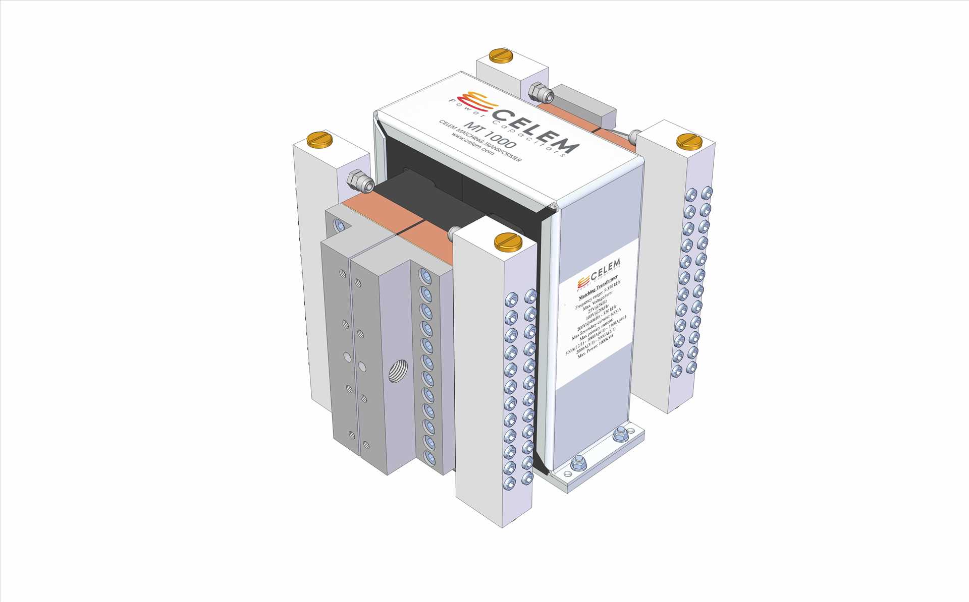
MT Matching Transformers are uniquely compact and provide an excellent step-down voltage solution for induction-heating systems.
The MT series creatively addresses the key characteristics of high quality matching transformers for high frequency / high power applications.
- The skin effect in the MT is negligible due to its unique laminar structure. Instead of the traditional copper tubes, the MT winding is made of laminar copper sheets. At 350 kHz this revolutionary structure reduces resistive losses by a factor of 10, and consequently increases overall efficiency to above 90%.
- The coupling coefficient of the MT is exceptionally high. Using alternating primary and secondary layers of thin copper sheets creates unprecedented coupling and very low reactive losses. The MT was designed to achieve zero stray inductance. This advanced design results in short circuit voltage of less than 10%, so that over 90% of the available reactive power is transmitted to the load.
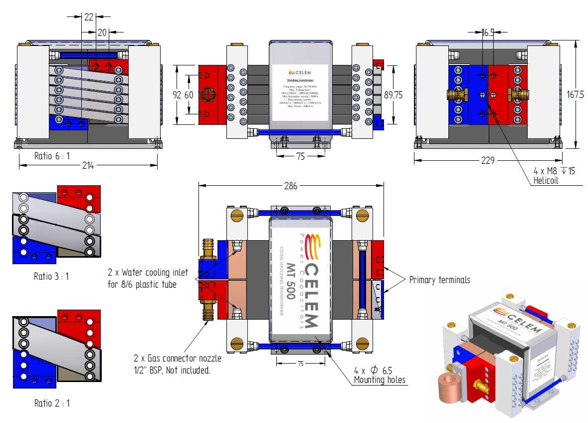
- The MT completely avoids de-rating of specification when tapped, through an innovative yet simple combination of identical coil elements that are connected in series and parallel. This enables the transformation ratio to be modified quickly and without power reduction.
- The frequency range of the MT is exceptionally wide: 5 – 350 kHz. This is made possible by practically eliminating stray inductance, as well as by using high saturation ferrite.
| TYPE | MT 250 | MT 300 | MT 500 | MT 1000 | ||||||||
| Dimensions (L x W x H) | mm | 287.5 x 228 x125 | 287.5 x 228 x170 | 287.5 x 228 x170 | 287.5 x 228 x 260 | |||||||
| Weight | kg | 18 | 22 | 26 | 45 | |||||||
| Tapping | ratio | 3:1 | 4:1 | 2:1 | 6:1 | 3:1 | 2:1 | 12:1 | 6:1 | 4:1 | 3:1 | 2:1 |
| Max Primary voltage | Vrms | 600 | 800 | 1200 | 1200 | |||||||
| Max secondary current | A | 1500 | 2000 | 3000 | 6000 | |||||||
| Max primary current | A | 500 | 500 | 1000 | 500 | 1000 | 1500 | 500 | 1000 | 1500 | 2000 | 3000 |
| Reactive power transfer | % | > 90% | > 90% | > 90% | > 90% | |||||||
| Active efficiency | % | > 95% | > 95% | > 95% | > 95% | |||||||
| Max power | kVA | 250 | 300 | 500 | 1000 | |||||||
| Stray inductance | μH | < 0.2 | < 0.3 | < 0.4 | < 1.5 | |||||||
| Frequency range | kHz | 20 - 350 | 20 - 350 | 20 - 350 | 5 - 350 | |||||||
| Double primary windings option* | √ | √ | √ | √ | ||||||||
| Iron Core option** | √ | √ | ||||||||||
- * Double primary windings option: It is possible to get the MT250, MT300, MT500 and the MT1000 with twice the number of the windings in the primary. With this option one can work at lower frequencies down to 10kHz in the MT250, MT300, and MT 500, and down to 2.5kHz in the MT1000. Note that with this option the maximum current in the primary is cut by a factor of 2.
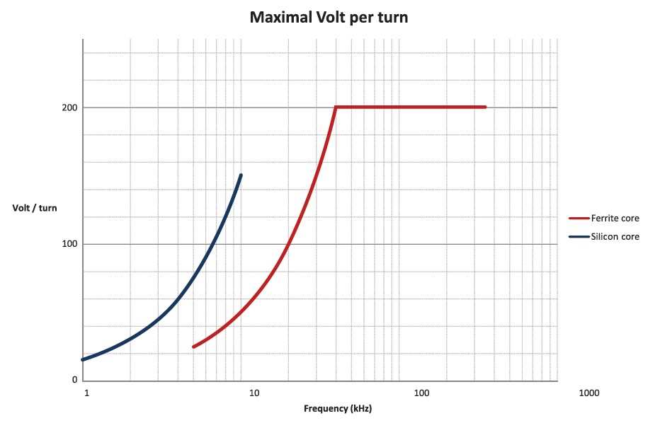
** Silicon Iron core option: It is possible to get the MT300 and the MT500 with a Silicon Iron core instead of the Ferrite core. This option enables low frequency operation (Maximal Volt/turn chart). It is possible to get the Silicon Iron core with the Double primary windings option.


