The New C-Cap Capacitor
- C-Cap has to be mounted mechanically to the bus-bar with 4 screws. Make sure that the top surface of the C-Cap forms a good thermal contact with the bottom bus-bar. It is a good practice to improve the thermal conductivity of this interface with thermal conductive paste.
- Use torque of 5 Nm when tightening the 4 M6 screws.
- C-CAp is suppplied with 4 SMC water connectors.
- Tightening torque specification for the large nut on the central rod is 8Nm. Be careful not to exceed 10Nm. Celem supply a special socket for tightening the nut at the required torque. Please check https://www.celem.com/socket_for_c-cap_m16_nut
- Bottom bus bar is usually not cooled directly, therefore Inlet cooling water should be connected to the top electrode as this electrode cools the bottom bus-bar.
- Water flow requirement varies with number of capacitors in the same water circuit and the power on each capacitor. When operating at maximum power, the electrodes of the C-cap should not exceed 40C degrees.
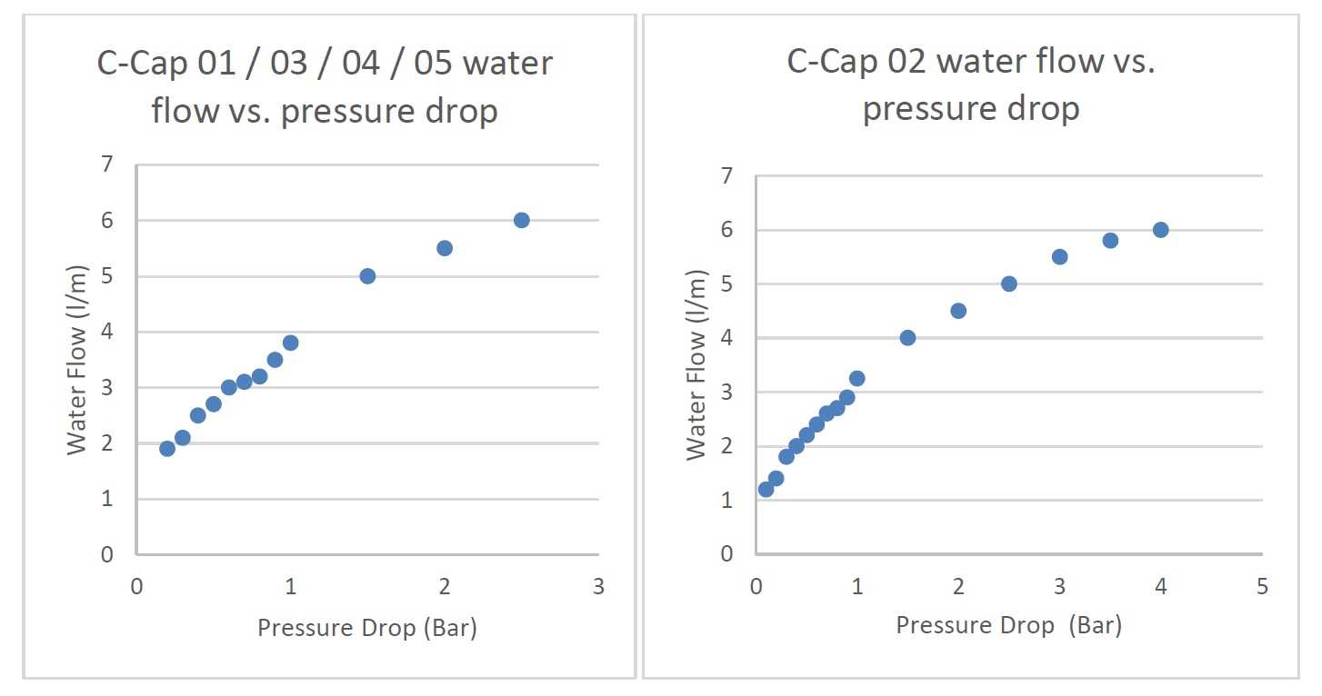
- The charts below depict the water flow vs. the water pressure drop on a C-cap when electrodes are chained in series.
- Starting from April 2019 every C-Cap will be equipped with a normally closed thermal switch that opens once the temperature of the capacitor raises above 55C. Customer can use this switch to get direct real time indication of any cooling issues and other malfunctions in the system.


